


Image Credit: Avago Technologies, Digi-Key, Newark
Fiber optic receivers convert light signals into electrical signals for use by equipment such as computer networks. These electro-optical devices consist of an optical detector, a low-noise amplifier, and signal conditioning circuitry. After the optical detector converts the incoming optical signal into an electrical signal, the amplifier increases it to a level suitable for additional signal processing. The modulation type and the electrical output requirements determine what other circuitry is required.
How Fiber Optic Receivers Work
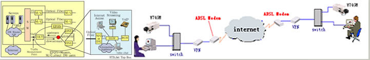
Fiber optic receivers use positive-negative junctions (PN), positive-intrinsic negative (PIN) photodiodes, or avalanche photodiodes (APD) as optical detectors. The incoming light signal is sent by a fiber optic transmitter (or transceiver) and travels along single-mode or multi-mode optical cable, depending on device capabilities. A data demodulator converts the light signal back into its original electrical form. In more complex fiber optic systems, wavelength division multiplexing (WDM) components are also used.

Figure 1 – Fiber Optic Receiver Block Diagram – Image Credit: Integrated Publishing
Semiconductors and Photodiodes
The GlobalSpec SpecSearch database allows industrial buyers to select products by semiconductor type and photodiode type. Two types of semiconductors are used in fiber optic receivers.
- Silicon semiconductors are used in short-wavelength receivers with a range of 400 nm to 1100 nm.
- Indium gallium arsenide semiconductors are used in long-wavelength receivers with a range of 900 nm to 1700 nm.
As described above, fiber optic receivers use three different types of photodiodes.
- P-N junctions are formed at the boundary of a P-type and N-type semiconductor, typically in a single crystal via doping.
- PIN photodiodes have a large, neutrally-doped intrinsic region sandwiched between P-doped and N-doped semiconducting regions.
- APDs are specialized PIN photodiodes that operate with high reverse bias voltages.
Amplifiers and Connectors
Fiber optic receivers use either low-impedance or transimpedance amplifiers.
- With low-impedance devices, bandwidth and receiver noise decrease with resistance.
- With trans-impedance devices, the bandwidth of the receiver is affected by the gain of the amplifier.
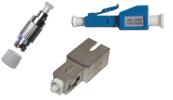
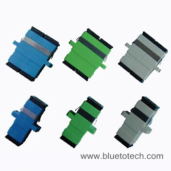
Typically, fiber optic receivers include a removable adaptor for connections to other devices. Choices include D4, MTP, MT-RJ, MU, and SC
Receiver Performance
When using GlobalSpec to source products, buyers should specify these parameters for fiber optic receiver performance.
- Data rate is the number of bits transmitted per second, and is an expression of speed.
- Receiver rise time is also an expression of speed, but indicates the time required for a signal to change from a specified 10% to 90% power.
- Sensitivity indicates the weakest optical signal that the device can receive.
- Dynamic range is related to sensitivity, but indicates the power range over which the device operates.
- Responsivity is the ratio of radiant energy in watts (W) to the resulting photocurrent in amperes (A).